

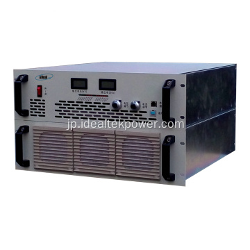
頑丈な高出力高電圧充電電源
最新の価格を取得する| お支払い方法の種類: | T/T |
| インコタームズ: | FOB,CFR,CIF,EXW |
| 最小注文数: | 1 Piece/Pieces |
| 輸送方法: | Ocean,Land,Air,Express |
| ポート: | SHANGHAI,NANJING,QINGDAO |

| お支払い方法の種類: | T/T |
| インコタームズ: | FOB,CFR,CIF,EXW |
| 最小注文数: | 1 Piece/Pieces |
| 輸送方法: | Ocean,Land,Air,Express |
| ポート: | SHANGHAI,NANJING,QINGDAO |
モデル: CCPS
ブランド: IDEALTEKNIC
原産地: 中国
出力電力: > 500W
出力タイプ: シングル
Input Voltage: Three Phase 380vac
Input Frequency: 50/60hz
Working Principle: Pwm
Power Supply Type: Igbt-Based
Working Mode: Constant Voltage / Constant Current
Display Mode: Lcd
Control Mode: 10-Turn Potentiometers
Protections: Input Lack Phase, Ovp, Ocp, Otp, Short-Circuit Protections Etc., Ocp, Short Circuit And Load Dischargin
Applications: Capacitor Charging, Electrostatic Precipitator, Semiconductor Process, Lab Test / Hipot / Capacitor Charging
Cooling: Forced Air Cooling
Circuit Mode: Pwm
Output Voltage Range: 5 Kv ~ 60 Kv
Output Current Range: 100 Ma ~ 2400 Ma
| 販売単位 | : | Piece/Pieces |
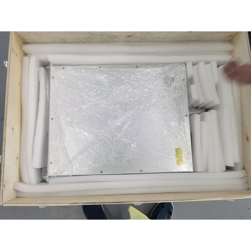
| パッケージ型式 | : | プライウッドケース |
| 写真の例 | : |
|
| ダウンロード | : |
|

CCPSシリーズ高電圧コンデンサ充電DC電源
概要概要
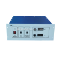
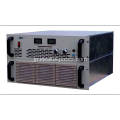
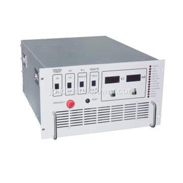
CCPS-6Uシリーズ高電圧電源は、CCP-6U高電圧コンデンサ充電電源のアップグレードバージョンです。最大10KWの出力電力と5KV / 10KV / 20KV / 30KV / 40KV / 50KV / 60KVの出力電圧レベルを備えた19インチ6U標準ラックマウントシャーシを使用し、高電圧充電電源が実現しました高効率、高出力応答速度、より高速な保護を維持し、自己回復を開始することに基づいて、ラックマウント型HVコンデンサ充電電源の充電容量が大幅に増加します。
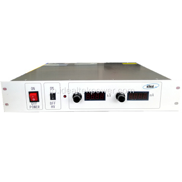
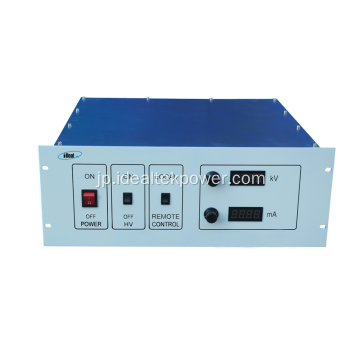
この一連のコンデンサ充電高電圧電源のフロントパネルは、ポテンショメータによって制御され、LCDメータは高電圧出力を示します。この一連のコンデンサ充電HVPSには、コンデンサ充電HVPSの動作パラメータを制御および監視するためのRS485インターフェースおよび制御ソフトウェアを装備できます。
電源には、入力位相損失、出力過電圧、過電流、過熱、短絡保護など、全負荷でのHVコンデンサ充電器の長期的かつ信頼性の高い動作を保証するためのより包括的な保護が装備されています。また、高電圧電源と被試験コンデンサを効果的に保護するために、高電圧の充電および放電条件に対処するための放電回路を装備しています。

特徴
l HVDC電源またはHVコンデンサ充電電源として使用できます。
l 出力電圧は0〜100%の範囲で調整可能
l 出力電力:5KJ / Sでの平均充電とピーク充電電力は12KWに達する可能性があります。
l 定電流モードで充電し、完全に充電されるまで定電流モードに切り替えます。
l 独自の二重絶縁システム、強力な干渉防止能力。
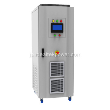
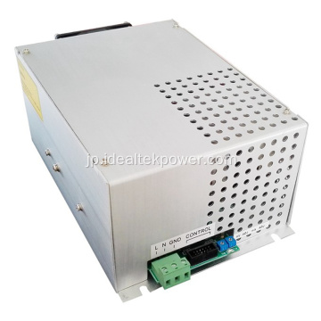
l 強制空冷、非常に頑丈なデザイン。
アプリケーション
コンデンサ充電、電気集じん器、半導体プロセス。
安全上の注意
1.このパワーモジュールはHV出力を備えており、専門家のみが操作できます。
2.操作前に十分な接地を確認してください。
3.コンデンサ充電電源の内部蓄積エネルギーが低いため、無負荷で動作させないでください。
4.電源モジュールを清潔に保ち、換気を良くします。
5.HV入力および出力コネクタまたはHV負荷は何にも触れません。
|
Input |
Connection mode |
Three-phase, four-wire (PE), TN-S supply mode |
|
|
Voltage |
380Vac±10% |
||
|
Frequency |
50Hz/ 60Hz ± 10% |
||
|
Current |
As per output power. |
||
|
Output |
Rated power |
6KW ~ 12KW (Max.) available ** |
|
|
Output voltage adjusting range |
5KV ~ 60KV available ** (For other output voltages, please contact us for details) |
||
|
Output current adjusting range |
0A ~ ****mA |
||
|
Output polarity |
Positive or Negative (both available) Client must choose one output polarity before ordering. |
||
|
Working mode |
Constant voltage (CV) / Constant current (CC) |
||
|
Accuracy (C.V.) |
Line regulation |
≤0.5% FS ± 1 digit (Output voltage change rate only caused by changes of input voltage over ± 10% range of variation) |
|
|
Load regulation |
≤1% FS ± 1 digit (Output voltage change rate only caused by full range load changes) |
||
|
Accuracy (C.C.) |
Line regulation |
≤0.5% FS ± 1 digit (Output voltage change rate only caused by changes of input voltage over ± 10% range of variation) |
|
|
Load regulation |
≤0.5% FS ± 1 digit (Output voltage change rate only caused by full range load changes) |
||
|
Temperature drift |
≤0.03% FS (Output voltage change rate every 8 hours after power on for half an hour) |
||
|
Ripple (p-p) |
≤0.5% FS (measured @ 80% ~ 100% rated output) |
||
|
Output cable |
HV connector and line provided by IdealTek. |
||
|
Efficiency |
≥90% |
||
|
Setting & Display |
Control mode |
Local |
10-turn potentiometer on front panel. |
|
Remote (Optional) |
RS485 communication interface. In line with MODBUS-RTU standard. The user can control and monitor the power supply via RS485 connection with computer, E.g: l Power ON / OFF l Output voltage & current setting & reading. l Working state monitoring (constant voltage, constant current, fault) |
||
|
Display mode |
41/2 LCD digital display |
||
|
Display error |
≤±0.5%FS ± 1digit (range: 5%~100% of the rated value) |
||
|
Display resolution |
As per output voltage & current values. |
||
|
Protection & Monitoring functions |
Input protection |
Input lack phase protection. |
|
|
Output over voltage protection (OVP) |
Power supply automatically cuts off output and alarms when output has over voltage. |
||
|
Output over current protection (OCP) |
Power supply automatically cuts off output and alarms when the output has over current. |
||
|
Over temperature protection (OTP) |
Power supply automatically cuts off output and alarms when the internal temperature of the power supply exceeds its threshold value. |
||
|
Output short-circuit protection |
Power supply automatically switches to CC working when the output has short-circuit. |
||
|
Over-loading capacity |
Withstand working with 1.05 times of rated current. |
||
|
Noise |
≤65dB |
||
|
Protection degree |
IP20 |
||
|
Cooling method |
l Forced air cooling l Forced air cooling + internal water-cooling loop. Direction: The lower part of the left and right sides - In and Top - Out wind. Differ as per output power rating. |
||
|
Inverter transient protection response time |
≤10us |
||
|
Working environment conditions |
Ambient temperature |
-5℃~+45℃ |
|
|
Humidity |
10%~80%(non-condensing) |
||
|
Height |
≤1000m |
||
|
Location |
Indoor use only No conductive dust, gas or steam that destroys the insulating medium No severe vibration and shock, good ventilation. |
||
|
Size (W*H*D) (mm) |
482*265.5*566.5 (19” 6U standard chassis) |
||
|
Weight |
Approx. 45Kg |
||
|
|
|||
|
Front panel description |
||||||||
 |
||||||||
|
No. |
Name |
Function |
Operation / display instruction |
|||||
|
F1 |
Control cabinet air inlet |
Control cabinet heat dissipation air inlet |
Keep it clean and smooth |
|||||
|
F2 |
Handle |
For moving and lifting purpose |
|
|||||
|
F3 |
Mounting hole |
For cabinet installing and fixing |
|
|||||
|
F4 |
POWER switch |
Supply electric ON/OFF switch |
Switch to ON position è Power ON Switch to OFF position è Power OFF |
|||||
|
F5 |
VOLTAGE |
Output voltage real-time display |
Digital LED display |
|||||
|
F6 |
CURRENT |
Output current real-time display |
Digital LED display |
|||||
|
F7 |
Indicator lights |
Real-time indication of module working state |
Indicator lights display |
|||||
|
F8 |
Voltage Adj. |
Output voltage adjusting |
Turn as icon, clockwise adjusting for increasing output voltage, anticlockwise adjusting for decreasing output voltage. |
|||||
|
F9 |
Current Adj. |
Output current adjusting |
Turn as icon, clockwise adjusting for increasing output current, anticlockwise adjusting for decreasing output current. |
|||||
|
F10 |
Analog port |
232/485 optional port (N/A for this unit) |
Please connect to DB9 port for communication with host. |
|||||
|
F11 |
Start/Stop (with lock) |
HV output start/stop |
Press down (green light ON) è HV START Press up (green light OFF) è HV STOP |
|||||
|
F12 |
Charging/Charged |
Charging / Charged state indicator light |
Charging lighted è Under charging. Charged lighted è Charging finished. |
|||||
|
Front Panel Indicator Lights Description |
||||||||
 |
||||||||
|
No. |
Name |
Function |
Operation / display instruction |
|||||
|
F13 |
Host indicator light |
Green LED light, lighted when power supply works as host unit under multi-unit parallel-working. Note: host indicator light lighted under single-unit working. |
Indicator lights display |
|||||
|
F14 |
Slave indicator light |
Green LED light, lighted when power supply works as slave unit under multi-unit parallel-working. Note: slave indicator light not lighted under single-unit working. |
Indicator lights display |
|||||
|
F15 |
C.V. indicator light |
Green LED light, lighted when power supply works under CV state. |
Indicator lights display |
|||||
|
F16 |
C.C. indicator light |
Green LED light, lighted when power supply works under CC state. |
Indicator lights display |
|||||
|
F17 |
Flashover indicator light |
Red LED light, lighted when power supply output has disruptive discharging. |
Indicator lights display |
|||||
|
F18 |
OC indicator light |
Red LED light, lighted when power supply has internal inverter output over current. |
Indicator lights display |
|||||
|
F19 |
Out short indicator light |
Red LED light, lighted when power supply has output short-circuits. |
Indicator lights display |
|||||
|
F20 |
OP indicator light |
Red LED light, lighted when output power of high voltage power supply exceeds the limit. |
Indicator lights display |
|||||
|
F21 |
Inhibit indicator light |
Red LED light, lighted when power output is prohibited by client's external nodes. |
Indicator lights display |
|||||
|
F22 |
OT indicator light |
Red LED light, lighted when power supply has internal module over temperature. |
Indicator lights display |
|||||
|
F23 |
Grid indicator light |
Red LED light, lighted when power supply has input abnormal (i.e.: lack phase or out of scope) |
Indicator lights display |
|||||
|
F24 |
IGBT indicator light |
Red LED light, lighted when power supply has internal inverter fault |
Indicator lights display |
|||||
|
F25 |
OV indicator light |
Red LED light, lighted when output voltage goes out of scope. |
Indicator lights display |
|||||
|
F26 |
Load OC indicator light |
Red LED light, lighted when output current goes out of scope. |
Indicator lights display |
|||||
|
F27 |
APS indicator light |
Red LED light, lighted when internal auxiliary power supply is working. |
Indicator lights display |
|||||
|
Back panel description |
||||||||
 |
||||||||
|
No. |
Name |
Function |
Operation / display instruction |
|||||
|
B1 |
GND |
Main circuit part, connected to earth. |
Separately connected to earth. |
|||||
|
B2 |
HV cabinet (Feedback) air socket |
For connection of HV cabinet and control cabinet. |
Connect to control cabinet (Feedback) air plug |
|||||
|
B3 |
Control cabinet (H-power) air socket |
For connection of control cabinet and HV cabinet. |
Connect to HV cabinet (H-power) air plug |
|||||
|
B4 |
Control cabinet input port |
Remote 485 signal input port |
Leave it unconnected if no 485 signal used. |
|||||
|
B5 |
Control cabinet DB9 port |
Remote control / reading port |
Connect in external analog signal for remote control / reading (i.e.: 0~10V) |
|||||
|
B6 |
Control cabinet DB15 port |
Remote start/stop, fault state TTL signal port |
Connect in external start/stop signal (i.e.: 24V) Connect in external analog signal for fault state indication (i.e.: TTL signal) |
|||||
|
B7 |
Control cabinet (Feedback) air socket |
For connection of control cabinet and HV cabinet |
Connect to HV cabinet (Feedback) air plug |
|||||
|
B8 |
Cooling fan (temperature-controlled) |
Exhaust fan, controlled by temperature inside the cabinet |
The higher the temperature inside cabinet, the faster the fan speed is. |
|||||
|
B9 |
IN 480V~600VDC |
Connects to DC480V~600V input |
Red is positive, black is negative. |
|||||
|
B10/11 |
HV-output |
Negative HV output connector |
Connection port |
|||||
|
B12 |
Power GND |
Positive output connector |
Connection port |
|||||
|
B13 |
HV cabinet (H-power) air socket |
For connection of HV cabinet and control cabinet. |
Connect to control cabinet (H-power) air plug |
|||||
|
Remote interface definition |
||||||||
|
|
||||||||
|
B4 Wiring diagram / B5 Internal wiring / B6 Wiring diagram |
||||||||
|
No. |
Name |
Function |
Operation / display instruction |
|||||
|
Z-1 |
485-A |
485-A |
485-A |
|||||
|
Z-2 |
485-B |
485-B |
485-B |
|||||
|
Z-3 |
Remote ON/OFF state node (optional) (N/A for this unit) |
ON/OFF state node + |
Power OFF, node closed Power ON, node open |
|||||
|
Z-4 |
|
ON/OFF state node - |
|
|||||
|
X1 |
Voltage remote control (optional) (N/A for this unit) |
Voltage remote control + |
0-10V signal for 0-15KV output voltage setting |
|||||
|
X2 |
|
Voltage remote control - |
|
|||||
|
X3 |
Current remote control (optional) (N/A for this unit) |
Current remote control + |
0-10V signal for 0-1000mA output current setting |
|||||
|
X4 |
||||||||
|
KV |
mA |
P (KW) |
Model |
KV |
mA |
P (KW) |
Model |
|
5 |
1200 |
6 |
CCPS-(N/P)6kW-5kV |
10 |
1200 |
12 |
CCPS-(N/P)12kW-10kV |
|
10 |
600 |
6 |
CCPS-(N/P)6kW-10kV |
15 |
800 |
12 |
CCPS-(N/P)12kW-15kV |
|
15 |
400 |
6 |
CCPS-(N/P)6kW-15kV |
20 |
600 |
12 |
CCPS-(N/P)12kW-20kV |
|
20 |
300 |
6 |
CCPS-(N/P)6kW-20kV |
30 |
200 |
6 |
CCPS-(N/P)6kW-30kV |
|
30 |
167 |
5 |
CCPS-(N/P)5kW-30kV |
40 |
150 |
6 |
CCPS-(N/P)6kW-40kV |
|
40 |
125 |
5 |
CCPS-(N/P)5kW-40kV |
45 |
133 |
6 |
CCPS-(N/P)6kW-45kV |
|
50 |
100 |
5 |
CCPS-(N/P)5kW-50kV |
50 |
120 |
6 |
CCPS-(N/P)6kW-50kV |
|
60 |
100 |
6 |
CCPS-(N/P)6kW-60kV |
60 |
200 |
12 |
CCPS-(N/P)12kW-80kV |
|
|
|||||||
l 0〜10Vアナログ信号制御(DBインターフェイス)(+AC)
l RS通信インターフェイス(RS232 / RS485オプション)(+RC)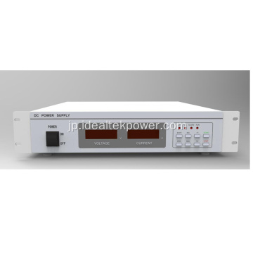


Privacy statement: Your privacy is very important to Us. Our company promises not to disclose your personal information to any external company with out your explicit permission.
Fill in more information so that we can get in touch with you faster
Privacy statement: Your privacy is very important to Us. Our company promises not to disclose your personal information to any external company with out your explicit permission.